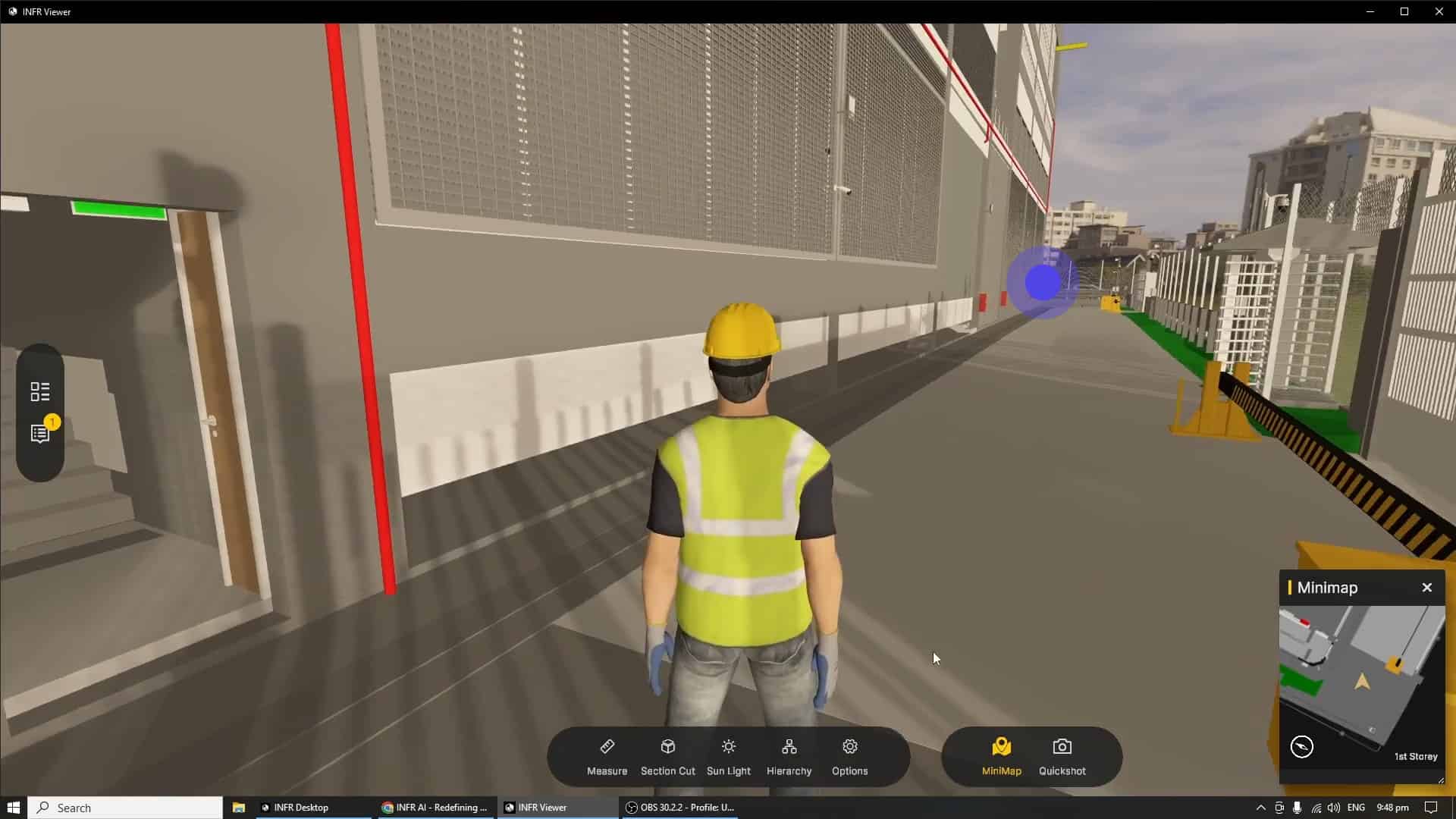
In this guide, we will go through the multiple ways in which your model can be viewed, from render modes to camera settings. Let's get started!
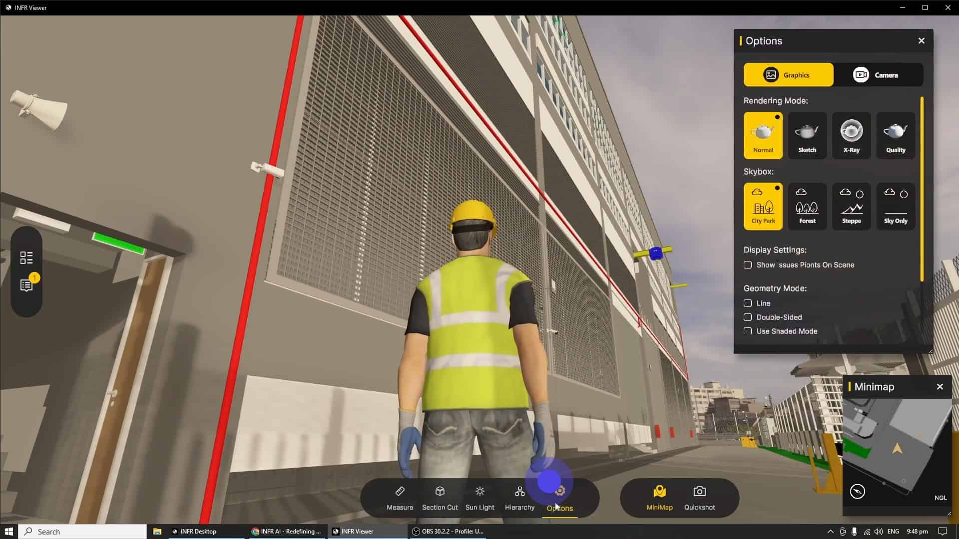
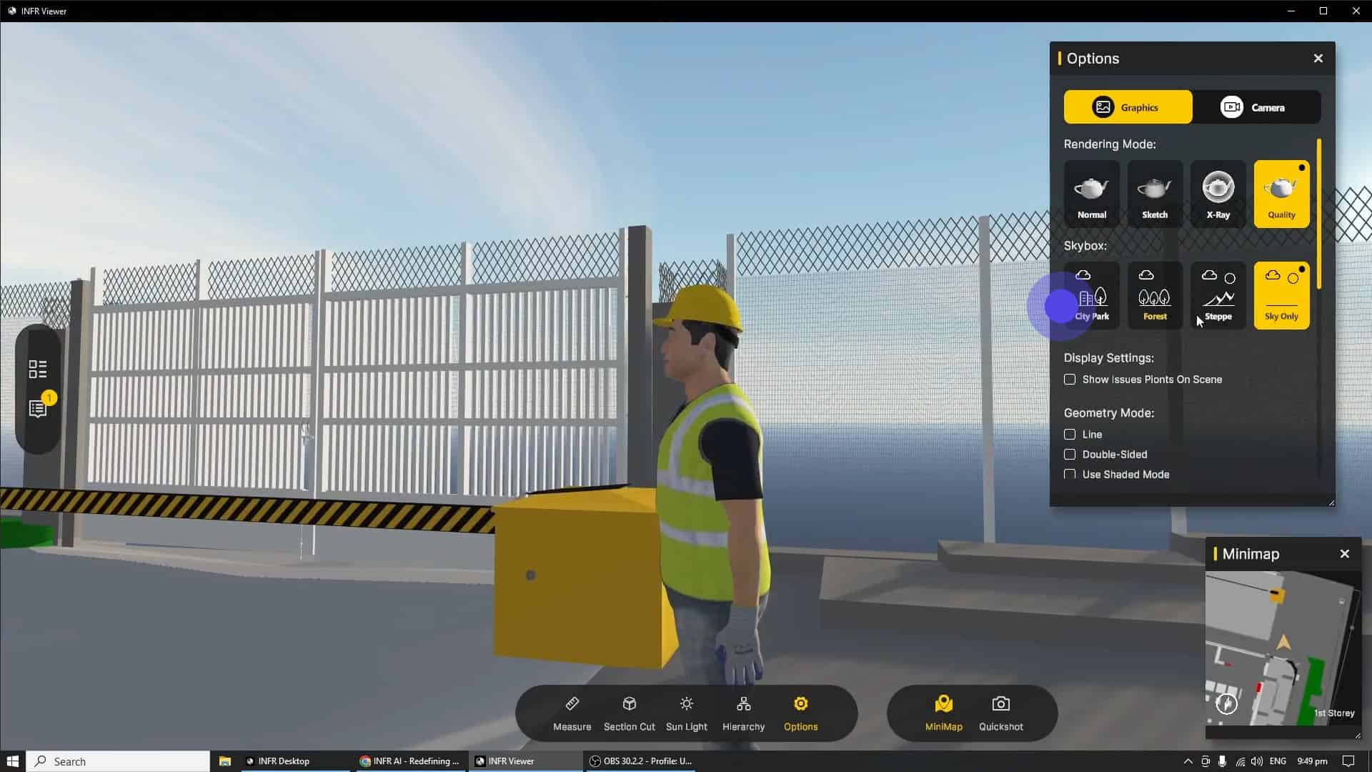
The "Graphics" sub tab can be accessed via the "Options" window, by clicking on it on the bottom toolbar.
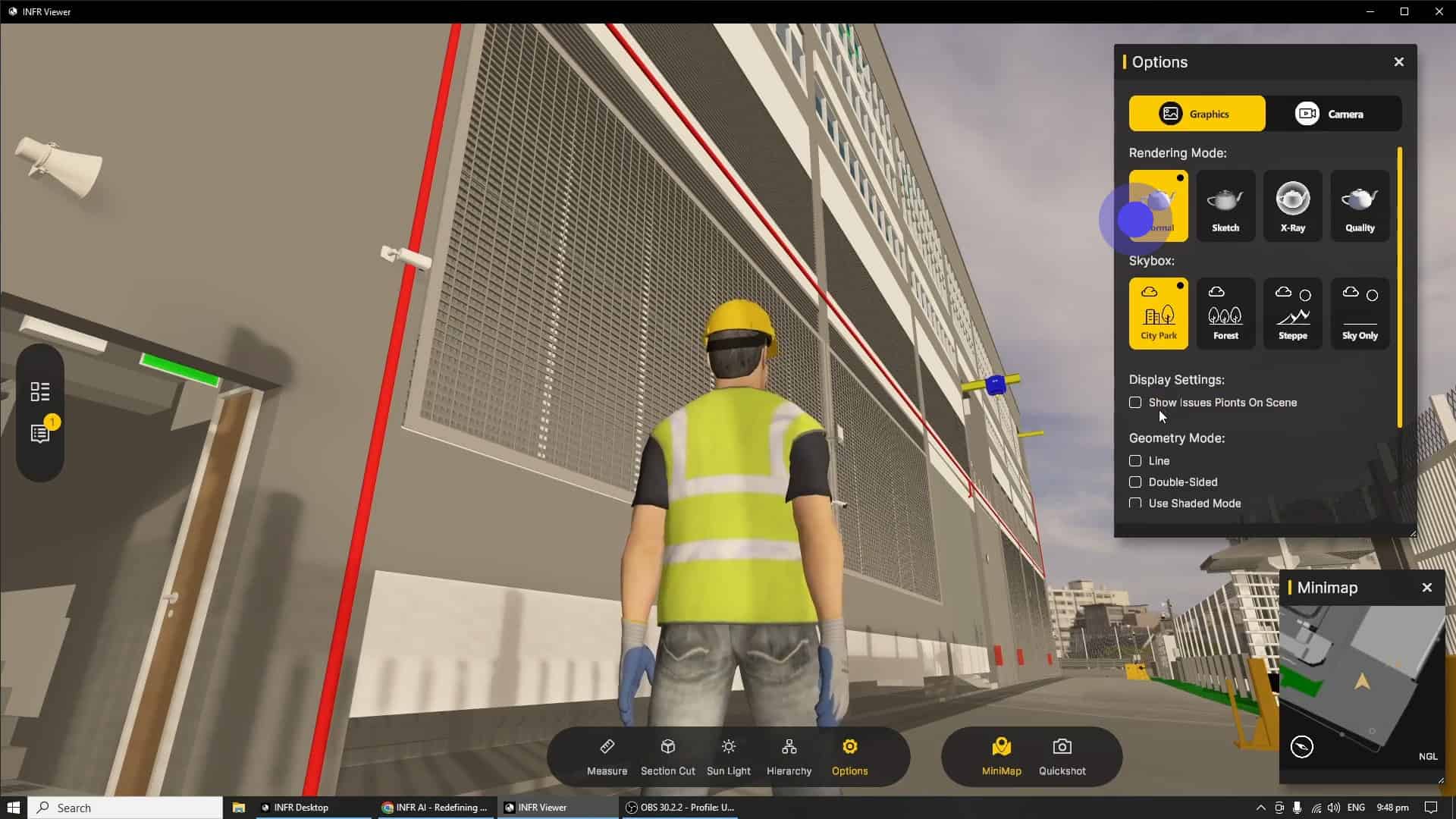
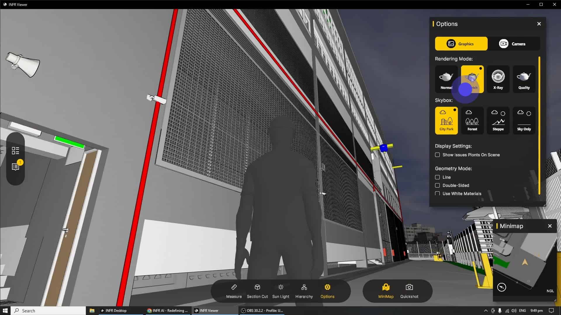
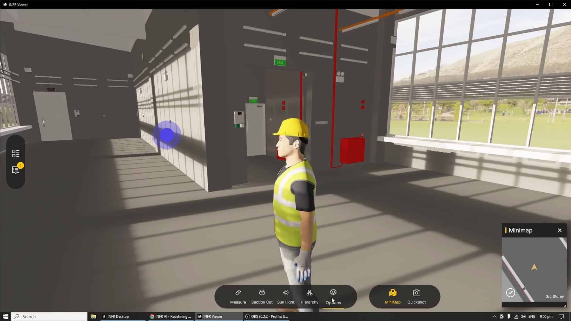
In the "Graphics" sub tab there are 4 rendering modes. "Normal" mode is activated by default, and renders your model in a manner that is the least taxing on your computer.
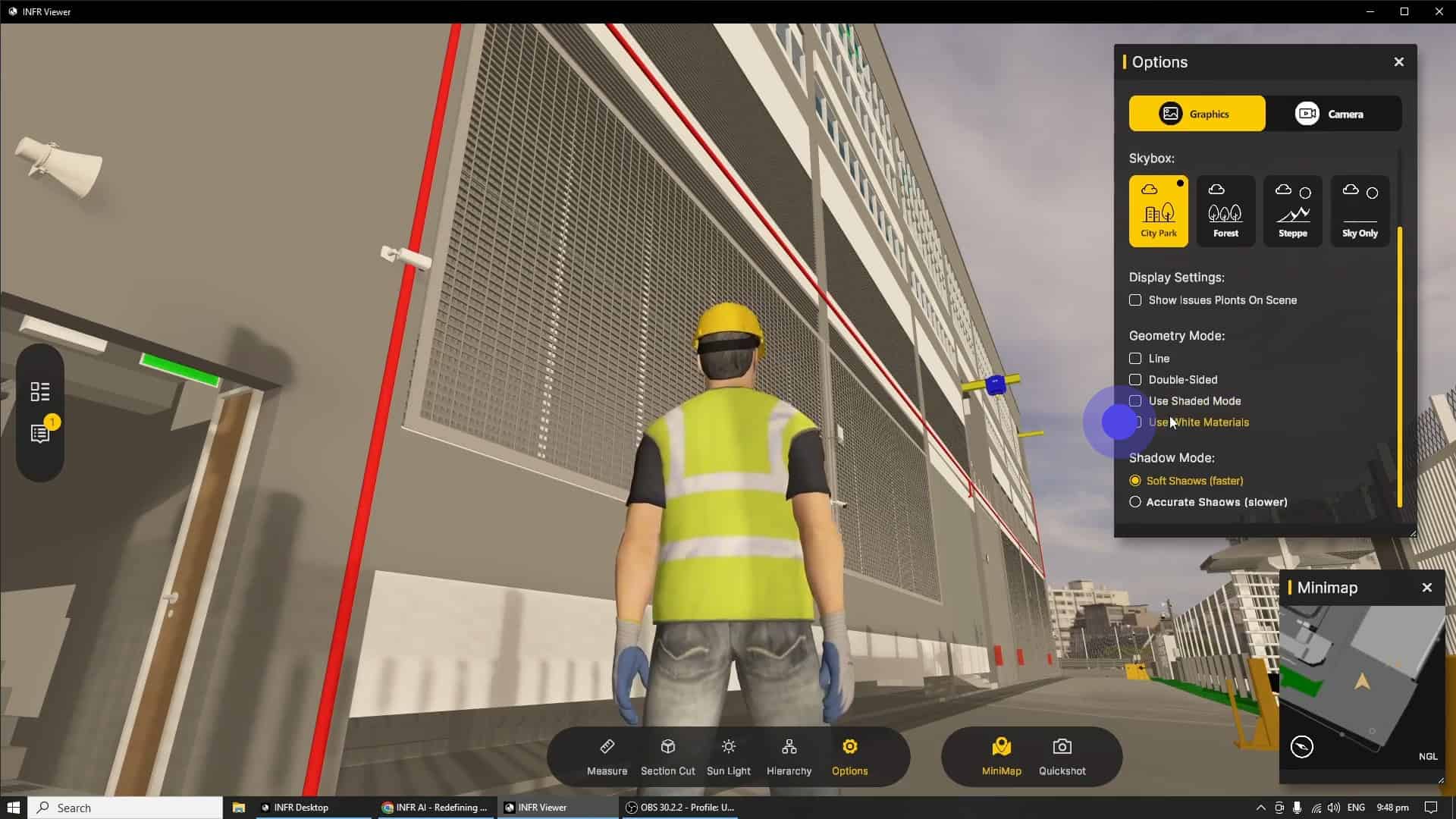
Each Render Mode has additional parameters that can be toggled for further fine tuning, this can be accessed by scrolling down the list when your mouse is hovering over the "Options" window.
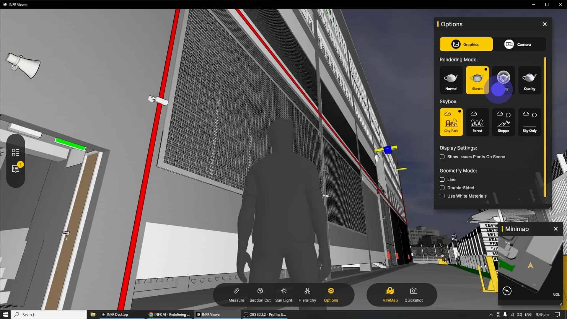
The "Sketch" Render helps stakeholders focus on space and design instead of material selection during the early design phases. Outlines helps users to see smaller objects such as valve wheels, door knobs and switches that one may have missed.
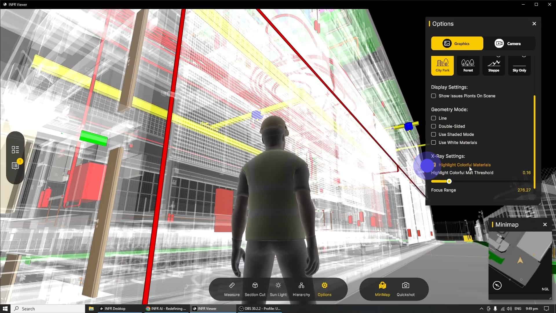
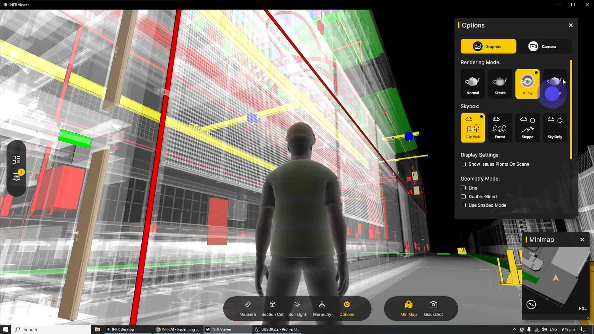
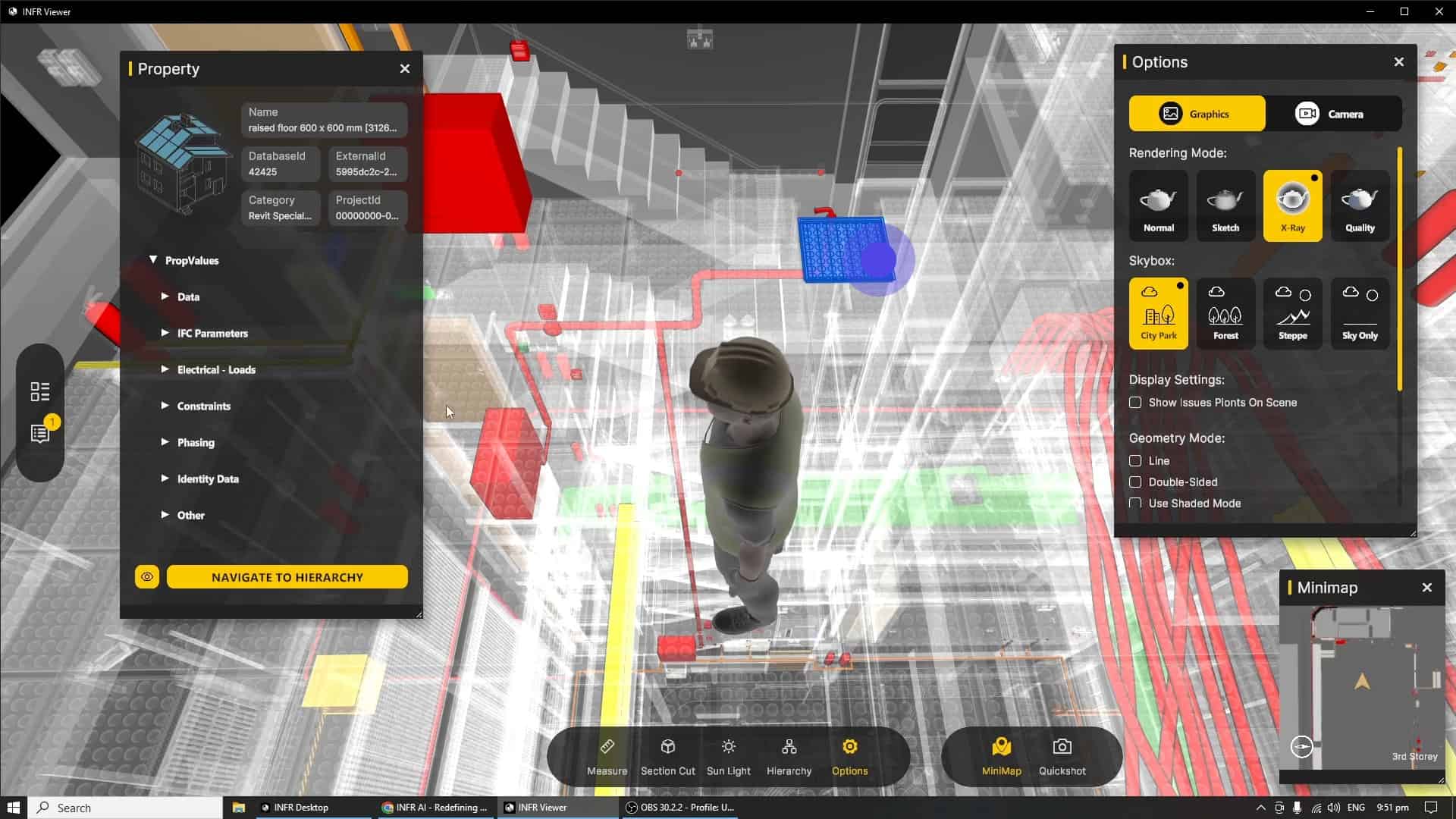
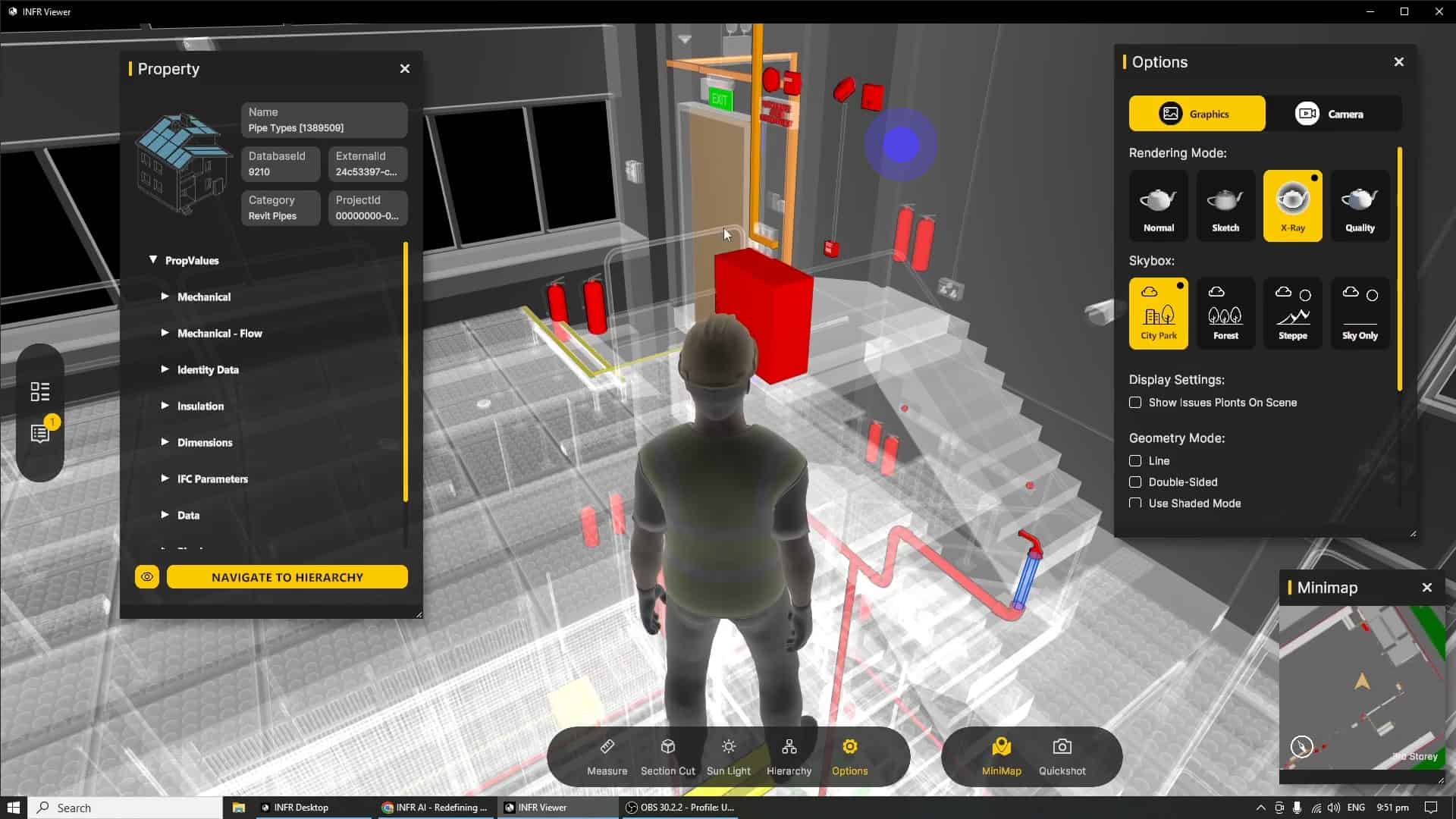
X-Ray Mode highlights the MEP systems located within your designs while still allowing for the contextual understanding of the other trades via a ghosted appearance. MEP color highlights are taken from shaded material appearances from your BIM model, with added grid functionality for models created by Autodesk Revit®.
Be sure to toggle the "Highlight Colorful Materials" option when using X-Ray Mode if your shaded coloured highlights are not appearing.
"Quality" Mode automatically beautifies your work by applying screen space reflections, ambient occlusions, soft shadows and material bump maps. Render the best version of your model in real time while still having one click access to the various coordination tools and technical features all at your fingertips.
Skyboxes are cosmetic enhancements that surround your model, the "City Park" option is selected by default, depicting an semi-urban setting which should fit the environment of most projects.
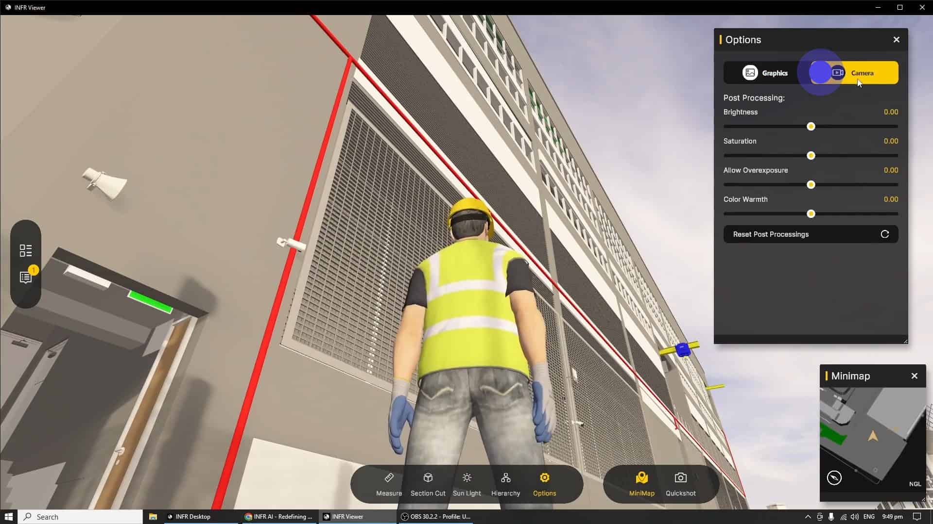
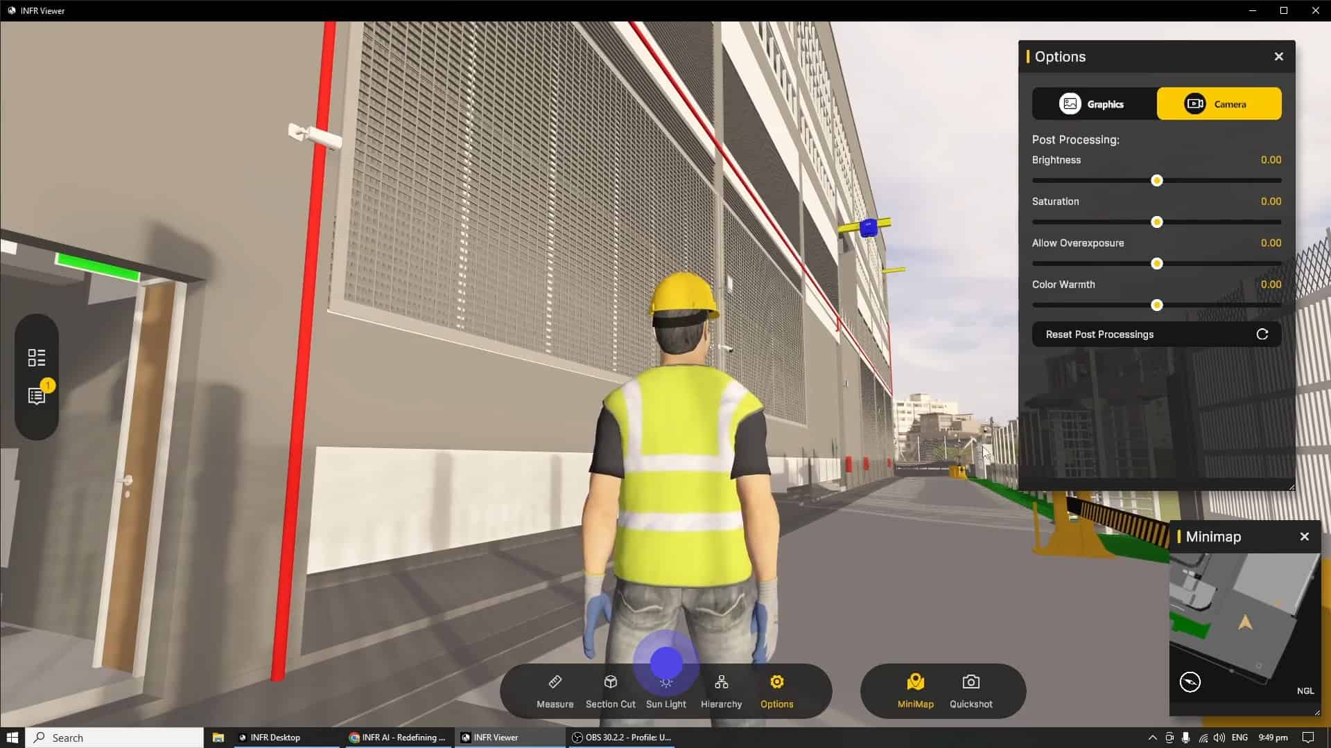
The "Camera" sub tab allows for basic fine tuning of visual parameters such as brightness, saturation, exposure, warmth; reset it to its default values by clicking on "Reset Post Processing"
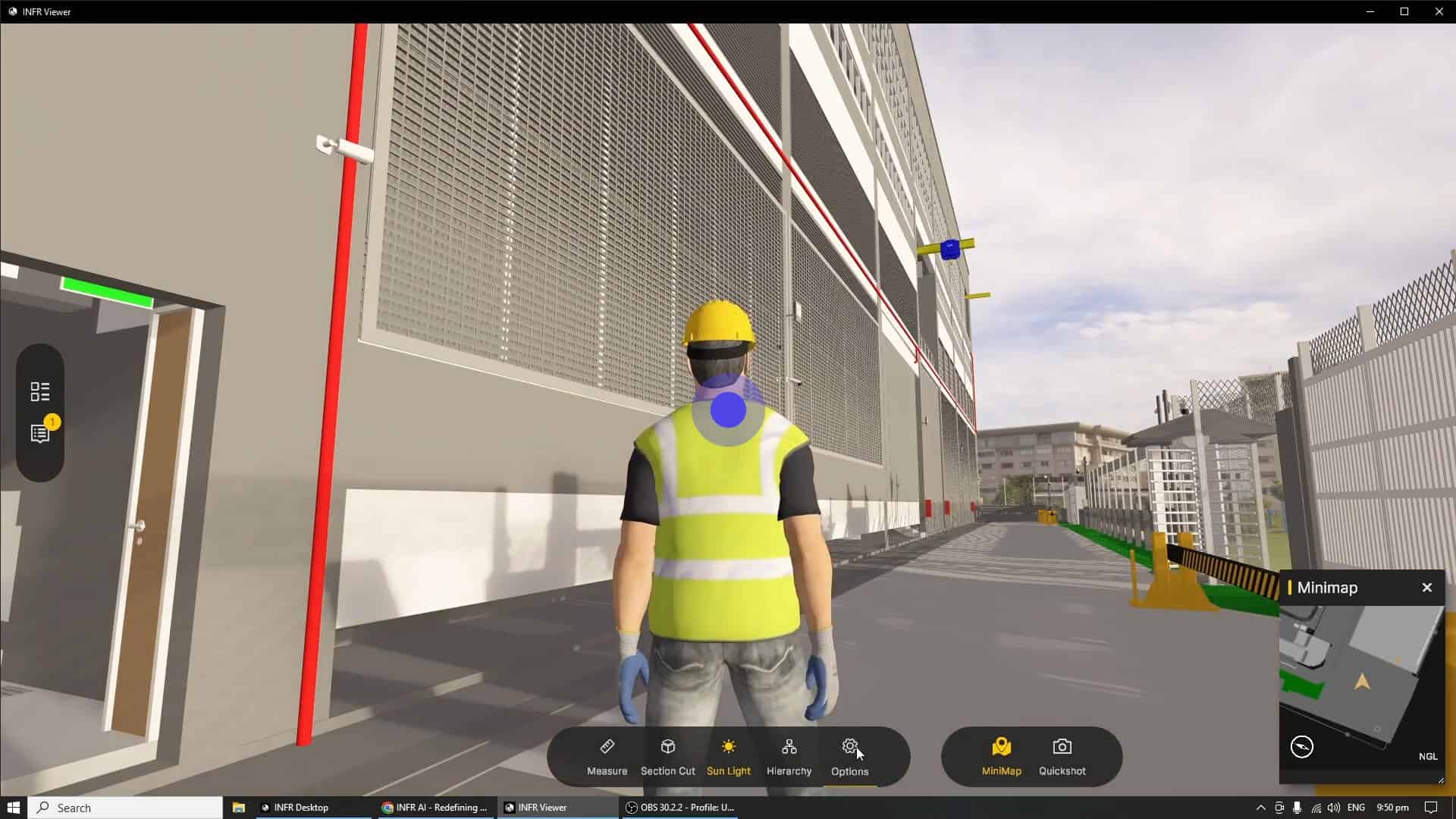
Lastly, the "Sunlight" tool in the bottom toolbar, allows the left mouse button hold to move the direction of the sunlight, this allows for both day and dusk lighting effects.
Now let us put all we have learnt so far with Navigation and Render Modes to explore what is possible within the INFR Desktop Viewer.
After smoothly navigating to an area under review, we are able to activate the X-Ray Mode to better inspect the design of critical systems in context with the other trades.
Render Modes and Navigation can also be used with tools such as BIM Metadata Inspection to look at systems that span multiple levels.
With that, we have concluded our quick start guide on graphics, the next chapter of this series will cover the bottom toolbar in more detail.